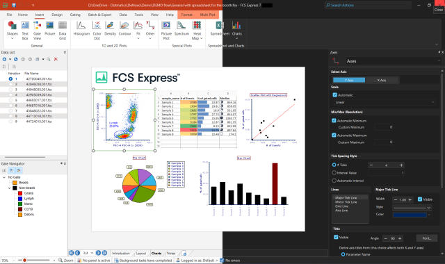
| 10. How does FCS Express implement
software compensation?
The emission spectrum (the wavelengths of light at which a given
fluorophore emits) generally overlaps several detection channels
of a typical commercial flow cytometer. Although most of the fluorescence
signal will be recorded in a single primary channel, it is common
that signal from the same fluorophore can be detected in two (or
sometimes more) secondary channels. Compensation is the process
of removing the unwanted fluorophore signal from secondary channels.
A classic example is that although the fluorescence from fluorescein
is primarily measured in the “green” channel (~530 nm),
a significant amount of fluorescein fluorescence can also be detected
in the “yellow” channel (~570 nm). Thus, if you are
trying to detect another fluorochrome in the “yellow”
channel (i.e. PE), the signal you observe in the “yellow”
channel will comprise fluorescence from both PE and FITC.
More information on compensation can be found at:
http://biology.berkeley.edu/crl/flowcytometry.shtml
http://flowcyt.salk.edu/howto/compensation/compensation-howto.html
In many flow cytometers, compensation is built directly into
electronics of the flow cytometer. This is typically called hardware
compensation or analog compensation. There would be dials or buttons
that would allow the user to change the compensation parameters before
acquiring the data.
The dial would typically be labeled something like:. FL2-%FL1,
Where FL2 is the total amount of fluorescence observed or measured
in the FL2 channel and the %FL1 is the percentage of fluorescence
measured in the FL2 channel that is from the FL1 fluorochrome.
By changing the dial, the user is changing the amount of fluorescence
from the FL1 fluorochrome to subtract from the total fluorescence
measured in the FL2 channel. For example, if the FL2-%FL1 value
was 20, this means that the true FL2 value is the observed FL2
value minus 20% of the observed FL1 value.
Manual (hardware) Compensation
FCS Express can mimic analog compensation through the use of
sliders. This is called manual compensation.
In the example below, we are going to manually apply compensation
to a sample that is already stained with both fluorescein and
PE. This is only to illustrate manual compensation in FCS Express.
For an experiment, the most accurate way of applying manual compensation
is using single stained controls or antibody capture beads stained
with your antibody-fluorochrome combination.
Figure 1 is a plot of a data file that is in obvious need of
compensation. The fluorescein fluorescence, detected primarily
in FL1-H, is spilling into the FL2-H channel. In addition, the
PE fluorescence, detected primarily in the FL2-H channel, is spilling
into the FL1-H channel.
Figure 1
If you right click on the plot you can create a new compensation
setting, as seen in Figure 2.

Figure 2
After giving the new compensation setting a name,
a set of sliders will appear, as seen in Figure 3.

Figure 3
The sliders that appear pertain to the axes that
are currently displayed on the plot. Beneath each slider is the
classic, albeit slightly confusing, formula describing what that
slider is doing. To the left of the slider is a picture showing
how the data will move if you increase the compensation value.
Increasing the compensation value is accomplished by moving the
slider to the right, and decreasing the compensation value is
achieved by moving the slider to the left.
The following pictures show the effects of increasing the FL2-H
- % of FL1-H slider.
|
15% Compensation
|
 |
|
25% Compensation
|
 |
|
35% Compensation
|
 |
In FCS Express you set the manual compensation identically
to the way you would set it in hardware. i.e. iteratively adjust
the compensation value to until you like the picture that you
get.
Automatic (software) Compensation
In addition to hardware compensation, the data can also be acquired
uncompensated and then compensated in software. The advantage
of this is that since you never compensate the raw data, you never
have to worry that you acquired the data with the wrong compensation
settings.
To use the automatic compensation feature of FCS Express it is
necessary to have data from single stained positive control cells
or from antibody capture beads for each parameter that requires
compensation
Software compensation works by solving the system of equations
described below:
Equation (1.5) can be written more succinctly as:
O = K X R

Thus, in order to find the real values for a given parameter,
we have to use the inverse matrix. The inverse matrix is a set
of coefficients that are multiplied by the observed signals. This
is equivalent to FCS Express determining the value of the dials
in manual compensation..
When you do automatic compensation in FCS Express. You see the
inverted matrix K-1 (often called the compensation
matrix) in the compensation screen . The non-inverted matrix K
is often called the spillover matrix. Right now, FCS Express does
not display the spillover matrix, which will be added in the future.
The spillover matrix is calculated internally from the means or
medians of your single stained controls.
However, to reiterate, there is no difference between how the
compensation matrix values are applied, and how manual values
would be applied. That is why you can still adjust "automatic"
compensation values using the sliders. It just gets very difficult
to compensate more than a few parameters "by eye". Also,
automatic compensation guarantees that the correct matrix coefficients
are calculated based on your single stained controls.
That being said, there is an important difference between how
compensation is usually implemented in hardware and the matrix
method. In hardware compensation there is usually no way to change
the coefficient from a single channel into itself.
from rearranging equation (1.3) you can see that

if either k21 or k12 is small, the first
term will be negligible. However, if both k21 and k12
are large, this first term becomes important. That is why, in
FCS Express, after you perform automatic compensation, you often
find that kxx is not exactly 1.
In FCS Express you can look at the crossover matrix from the
compensation screen. It displays the matrix as source and target
values. Source is where the fluorescence is coming from, target
is where the fluorescence is appearing. The kxx value
appears where there source and target are the same. If you do
not see a value where the source and target are the same, FCS
Express is assuming that the crossover value for kxx
is 100%.
Please be aware that you are not compensating properly if you
change the values that FCS Express calculates for the compensation
matrix, assuming the correct single stained and negative control
data were used.
For a more practical discussion on how to set up automatic compensation,
please see our compensation
tutorial.
|